RJG Explains the Difference Between Hydraulic, Specific and Cavity Pressure
In this blog, process support and training provider RJG Technologies explains the difference between hydraulic, specific and cavity pressure and why each one matters.
Not all pressure is created equal. There are various parts of the injection moulding machine where we monitor pressure, and it’s important to look at each one individually to better understand what is happening to the plastic inside the mould.
Let’s review the three types of pressure on the machine (hydraulic, specific and cavity) and what makes them different (intensification ratio and pressure loss).
Types of Pressure
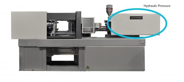
Hydraulic Pressure: The pressure in the injection cylinder is generated by the resistance to the flow of oil delivered by a hydraulic pump.
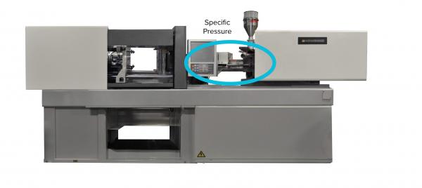
Specific Pressure: Also known as injection or plastic pressure, this is the actual material pressure within the screw and barrel assembly generated by a resistance to the flow of plastic in front of the screw during injection. Typically, hydraulic injection moulding machines display hydraulic oil pressure. Some will also display specific pressure. Servo-electric injection moulding machines display specific injection pressure, not hydraulic oil pressure.
Specific pressure is important to know because it allows you to document the pressure of the plastic at injection and select a capable machine.
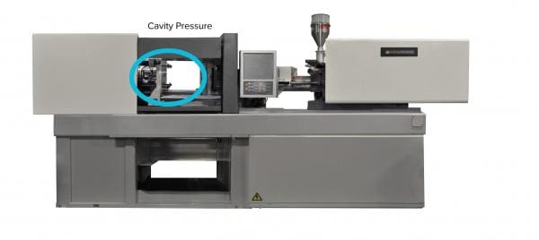
Cavity Pressure: The actual material pressure inside the moulding cavities themselves. In order to measure this, the mould must be instrumented with pressure sensors.
So what is the difference between these? Shouldn’t the pressure be the same for all of them? Nope.
If you look at an injection moulding process control system (such as the CoPilot), you can see that the measurements between these three pressure types vary greatly. That is due to the intensification ratio and pressure loss.
Intensification Ratio
The intensification ratio is the ratio between the area of the injection cylinder to the area of the screw tip assembly. The injection cylinder will always be larger, and the screw tip assembly will always be smaller, so that intensifies the pressure.
Think of it as using a cutting board to pound in a nail versus using a hammer. You could put the same amount of force behind it, but the hammer is going to transfer more pressure because there is less space for the energy to spread.
Every injection moulding machine has an intensification ratio. It is important to know this ratio prior to setting up a process. In order to determine the intensification ratio, a simple formula can be used:
Pressure Loss
Pressure loss is when you (you guessed it) lose pressure while filling a part. Pressure starts to decrease the minute it exits the nozzle.
When plastic exits the nozzle, it is at a significantly higher pressure than when it reaches the gate. We lose pressure through the orifice of the nozzle tip, the sprue, the runner system and the gate. The further away from the barrel you get, the lower the pressure. So as you can imagine, cavity pressure is significantly lower than specific pressure.
Conclusion
Taking into consideration hydraulic, specific and cavity pressures as well as intensification ratio and pressure loss, you can get a pretty clear picture of what is happening to the plastic as it moves through the injection moulding machine.
RJG
+44 (0)1733 232211
Website
Email


